Rephasor
Overview
This algorithm implements a rephasor, an operation that
dynamically resynthesizes an input phasor signal
(such as phasor) with a scaling value that
allows the rate of the phasor to be changed proportionally
to the input signal. This phasor also apply automatic
correction to prevent clock drift accumulation.
While phasors are typical signals used for table-lookup oscilators (oscf is a phasor-driven oscillator), phasors being used with rephasors are intended to be used as timing signals, similar to that of metro.
What is Drift?
clock drift, or drift, refers to what happens when
two independent clocks fall out of synchronization with
eachother, despite being set to the same rate. Drift
is most often a result of numerical errors accumulated
over time.
Rephasors intentionally use truncation to produce
phasors with clean resets to zero, rather than using
wraparound. This makes for a much cleaner timing signal,
but can quickly introduce drift.
Floating point operations can introduce some level of numerical error. It is not yet been formally tested how much this contributes to clock drift.
Clock drift build-up over time in a rephasor is mitigated by "checking in" with the external phasor signal, measure how much error there is, and compensating with "course correction".
Theory
To best understand how the rephasor works, some crude mathematical notation is adopted. This will serve as the basis of the C implementation, though some aspects will be reworked to be more optimized.
A phasor is a periodic rising ramp signal, normalized to
be in the range 0 and 1.
A phasor  will be defined in terms of an increment value
  :
:
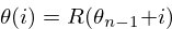
The function  is used to reset the phasor back to zero every time
it exceeds 1, discarding any numerical values that exceed 1.
For this reason, this phasor can be referred to as
a
is used to reset the phasor back to zero every time
it exceeds 1, discarding any numerical values that exceed 1.
For this reason, this phasor can be referred to as
a truncated phasor.
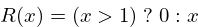
The truncation method can be defined using the following C-style teritiary notation:
NOTE: the sndkit phasor wraps around
values exceeding 1. One could call the sndkit phasor a
wraparound phasor.
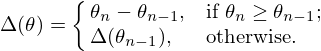
The delta function  will
return the difference the difference between the previous
sample and current sample of a given phasor. This
returns the increment value. When a phasor resets, the
last valid value is returned.
will
return the difference the difference between the previous
sample and current sample of a given phasor. This
returns the increment value. When a phasor resets, the
last valid value is returned.
This function can be mathematically defined as a recursive function, though the C implementation is much more straight forward.
A so-called rephasor can be defined as
 :
:
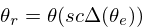
This works by resynthesizes an external
phasor signal  by obtaining the increment value via
the delta function, and using that to generate a new
phasor. This new increment value can also scaled using
a scaling value
by obtaining the increment value via
the delta function, and using that to generate a new
phasor. This new increment value can also scaled using
a scaling value  . A scaling
value of 2 makes the phasor 2 times faster, a scaling value
of 0.5 makes the phasor 2 times slower. Finally, there is
a correction coefficient
. A scaling
value of 2 makes the phasor 2 times faster, a scaling value
of 0.5 makes the phasor 2 times slower. Finally, there is
a correction coefficient  that is used for course correction, and is the key component
that makes the rephasor stay synchronized with the external
phasor.
that is used for course correction, and is the key component
that makes the rephasor stay synchronized with the external
phasor.
Correction works by measuring the amount of error that the
rephasor has. To do this, a comparison phasor signal
 is produced
by putting the main rephasor signal into another rephasor
that inverts the scaling value.
is produced
by putting the main rephasor signal into another rephasor
that inverts the scaling value.
This should return a reconstructed version of the external phasor. It is important to note a rephasor adds a unit-sample delay. Since two rephasors are used, a delay of 2 samples is introduced.
Using DSP z-notation to denote delay, the correction coefficient can be defined as ratio between the external signal and the correction signal:

The correction coefficient tends to be a value close to 1. When the value is greater than 1, it tells the rephasor to speed up. When it is less than one, it tells the rephasor to slow down.
This mathematically defines everything required for the C implementation.
Tangled Files
Tangles to rephasor.c and rephasor.h.
SK_REPHASOR_PRIV exposes structs.
#ifndef SK_REPHASOR_H
#define SK_REPHASOR_H
#ifndef SKFLT
#define SKFLT float
#endif
<<typedefs>>
#ifdef SK_REPHASOR_PRIV
<<structs>>
#endif
<<funcdefs>>
#endif#include <math.h>
#define SK_REPHASOR_PRIV
#include "rephasor.h"
<<funcs>>Struct
Definition
State is managed in a struct called sk_rephasor.
typedef struct sk_rephasor sk_rephasor;The struct will adopt constants based on the mathematical symbols defined above. It may be helpful to review that section.
pr, pc, and pe are cached phasor signals,
representing
,
, and
,
respectively. pc and pe are arrays of 2 samples because
of the 2-sample delay needed to compute the correction
coefficient.
The c variable is the correction coefficient
.
The variables s and si implement the scaling variables
and the inverse
 , which is stored
to shave off a
, which is stored
to shave off a 1/x division operation.
Rephasors need to cache increment values, which are stored
in ir and ic, for the main rephasor
and the comparison phasor
.
struct sk_rephasor {
    SKFLT pr;
    SKFLT pc[2];
    SKFLT pe[2];
    SKFLT c;
    SKFLT s;
    SKFLT si;

    SKFLT ir;
    SKFLT ic;
};
Initialization
Initialized with sk_rephasor_init.
void sk_rephasor_init(sk_rephasor *rp);Generally speaking, most things are zeroed out. The scalar values and correction coefficient are used as scalars, set to be 1 in order to be netural.
void sk_rephasor_init(sk_rephasor *rp)
{
    rp->pr = 0;
    rp->pc[0] = 0;
    rp->pc[1] = 0;
    rp->pe[0] = 0;
    rp->pe[1] = 0;
    rp->c = 1.0;
    rp->s = 1.0;
    rp->si = 1.0;

    rp->ir = 0.0;
    rp->ic = 0.0;
}
Setting the scaling value
Called sk_rephasor_scale.
void sk_rephasor_scale(sk_rephasor *rp, SKFLT scale);If this is a new scaling value, set the s and the siparameters.
void sk_rephasor_scale(sk_rephasor *rp, SKFLT scale)
{
    if (scale != rp->s) {
        rp->s = scale;
        rp->si = 1.0 / scale;
    }
}
Compute
Main Compute Function
A sample of audio is computed with sk_rephasor_tick, where
ext is an external phasor signal.
SKFLT sk_rephasor_tick(sk_rephasor *rp, SKFLT ext);The code below is an implementation based on the mathematical definition defined previously. Some code comments have been made in an attempt to connect the points.
/* implementation of a truncated phasor */

static SKFLT phasor(SKFLT phs, SKFLT inc)
{
    phs += inc;

    if (phs > 1.0) return 0;

    return phs;
}

SKFLT sk_rephasor_tick(sk_rephasor *rp, SKFLT ext)
{
    SKFLT pr, pc;
    SKFLT out;


    /* delta function of \theta_e */
    if (ext > rp->pe[0]) {
        rp->ir = ext - rp->pe[0];
    }

    /* compute main rephasor \theta_r */
    pr = phasor(rp->pr, rp->s * rp->ir * rp->c);

    /* delta function of \theta_r */
    if (pr > rp->pr) {
        rp->ic = pr - rp->pr;
    }

    /* compute rephasor \theta_c */
    pc = phasor(rp->pc[0], rp->si * rp->ic);

    /* compute correction coefficient */
    if (rp->pc[1] != 0) {
        rp->c = rp->pe[1] / rp->pc[1];
    }

    <<bounds_checking>>

    out = pr;

    /* update state */

    rp->pr = pr;

    rp->pc[1] = rp->pc[0];
    rp->pc[0] = pc;

    rp->pe[1] = rp->pe[0];
    rp->pe[0] = ext;

    return out;
}
Bounds Checking
As it turns out, the correction mechanism is rather brittle in practice. For example, it was very easy to break the rephasor with a steady input signal at around 73 BPM and a scaling value of 0.25 (4x slower).
To circumvent this, the rephasor will reject very high or very low values computed. Anything out of these bounds is probably wrong.
if (rp->c > 2.0 || rp->c < 0.5) rp->c = 1.0;No-sync computation
sk_rephasor_tick_nosync will compute a rephasor without
any of the corrections done for synchronization. This is
included as a way to compare implementations. By itself,
it's probably not all that useful.
SKFLT sk_rephasor_tick_nosync(sk_rephasor *rp, SKFLT ext);NOTE: flip-flopping between sk_rephasor_tick_nosyncand sk_rephasor_tick in a single instance of
rephasor is probably not a good idea.
SKFLT sk_rephasor_tick_nosync(sk_rephasor *rp, SKFLT ext)
{
    SKFLT out;

    if (ext > rp->pe[0]) {
        rp->ir = ext - rp->pe[0];
    }

    rp->pr = phasor(rp->pr, rp->s * rp->ir);
    rp->pe[0] = ext;

    out = rp->pr;

    return out;
}