The Oscillator
Introduction.
This document will describe an implementation of a classic table-lookup oscillator with linear interpolation.
The algorithm for this is an interesting mix of numerical processing, with the phasor being implemented in fixed point, and everything else being done in floating point. A big advantage to doing it this way is numerical stability: there is no risk of any phase accumulation or truncation like you'd get with floating-point. This is an important characteristic needed for phasor to avoid things like drift over time. As will be seen later, the fixed-point approach can be a little bit harder to understand, especially for those unfamiliar with fixed-point DSP. The author has put extra effort to explain these portions as clearly as possible.
The implementation also has a famous limitation of only being able to take in tables with sizes that are a power of 2.
Generated Files
Header:
#ifndef SK_OSC_H
#define SK_OSC_H
#ifndef SKFLT
#define SKFLT float
#endif
<<typedefs>>
#ifdef SK_OSC_PRIV
<<structs>>
#endif
<<funcdefs>>
#endif
C file:
#include <stdint.h>
#include <stdlib.h>
#include <math.h>
#define SK_OSC_PRIV
#include "osc.h"
<<static_funcdefs>>
<<constants>>
<<funcs>>
Top-level functions
The table-lookup oscillator is initialized with
sk_osc_init. The following arguments must be provided:
osc is a pre-allocated struct of sk_osc.
sr is the sampling rate.
tab is a pre-allocated wavetable, an array of SKFLTfloating-point values.
sz is the array size of the wavetable wt.
iphs provides the initial phase of the oscillator. It is
a value between 0-1.
void sk_osc_init(sk_osc *osc, int sr, SKFLT *wt, int sz, SKFLT iphs);To compute a sample of audio, use sk_osc_tick.
SKFLT sk_osc_tick(sk_osc *osc);This oscillator has 2 main parameters: frequency (freq), and amplitude (amp). They can be set with the following functions.
void sk_osc_freq(sk_osc *osc, SKFLT freq);
void sk_osc_amp(sk_osc *osc, SKFLT amp);void sk_osc_freq(sk_osc *osc, SKFLT freq)
{
osc->freq = freq;
}
void sk_osc_amp(sk_osc *osc, SKFLT amp)
{
osc->amp = amp;
}Constants
#define SK_OSC_MAXLEN 0x1000000L
#define SK_OSC_PHASEMASK 0x0FFFFFFL
Struct and Constants
The main struct of this oscillator is called sk_osc.
typedef struct sk_osc sk_osc;struct sk_osc {
<<sk_osc>>
};SKFLT freq, amp;
SKFLT *tab;
int inc;
size_t sz;
uint32_t nlb;
SKFLT inlb;
uint32_t mask;
SKFLT maxlens;
int32_t lphs;The oscillator stores it's main parameters freq and ampas floating point parameters. They are set to be values
440 and 0.2 by default.
osc->freq = 440;
osc->amp = 0.2;
A reference to the table is stored in the variable tab,
with its size sz.
osc->tab = wt;
osc->sz = sz;
A table lookup oscillator indexes through the table using
the increment rate stored in the integer value inc. This
value can be positive or negative. Is is zeroed out at
init-time.
osc->inc = 0;The variable lphs stores the phase position of the
previous sample. The initial phase value iphs is
multiplied with the the maximum table value, and then
masked to keep values in range.
osc->lphs = ((int32_t)(iphs * SK_OSC_MAXLEN)) & SK_OSC_PHASEMASK;For the fixed point table-lookup, some constants are derived and stored.
Phasor position is stored by splitting the bits of an N-bit integer number into two parts. The upper bits store the integer portion, while the lower bits store fractional portion. The maximum number of bits is arbitrary, but the underlying architecture must be able to accomodate for the width. In this implementation, the phasor uses 28 bits inside of a 32-bit number. This implicitely means the largest value can be
Split in the phasor position is measured by counting the
number of lower bits. This value is stored in the variable
nlb. This value is calculated with the equation
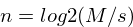
Where n is the number of lower bits, M is the maximum
wavetable size, and s is the size of the wavetable.
To calculate nlb, and hand-rolled log2 function is
created.
Smaller values of s mean more bits in the fractional
component of the number.
{
    uint32_t tmp;
    tmp = SK_OSC_MAXLEN / sz;
    osc->nlb = 0;
    while (tmp >>= 1) osc->nlb++;
}
<<calculate_mask>>
<<calculate_inlb>>
<<calculate_maxlens>>
The mask is the lower-bits masking variable. When an AND
operation is used against this constant, it filters out all
the upper bits, so only the lower bits can pass through.
This constant is necessary for being able to extract the
lower bits from the fixed-point phase value representation.
This sort of value is known in the bit-twiddling world as a
mask. In binary, all the lower bits up to the number of
lower bits are set to be on, with the remaining bits set
to be 0.
osc->mask = (1<<osc->nlb) - 1;The inverse of max lower bits value, or $1/2^{nlb}$, is stored as a constant. This cached value is used to replace and divide operation with a multiply operation, which has traditionally been a cheaper operation to do on a computer.
osc->inlb = 1.0 / (1<<osc->nlb);The constant maxlens is the maximum table length in units
of seconds. This is a value used to efficiently convert the
frequency parameter to sample increment value.
osc->maxlens = 1.0 * SK_OSC_MAXLEN / sr;Initialization
In addition to setting variables, the init function will also set the starting phase of oscillator.
void sk_osc_init(sk_osc *osc, int sr, SKFLT *wt, int sz, SKFLT iphs)
{
    <<osc_init>>
}
Computation
The meat of the algorithm is here. Here outlines the
tick function, where a single sample of an oscillator
is computed.
SKFLT sk_osc_tick(sk_osc *osc)
{
    SKFLT out;
    SKFLT fract;
    SKFLT x1, x2;
    int32_t phs;
    int pos;

    out = 0;
    <<update_increment_amount>>
    <<lookup_values>>
    <<obtain_fractional_component>>
    <<interpolate_values>>
    <<update_the_state>>
    return out;
}
First, the increment amount inc is updated.
The increment amount tells how much further to move the read
pointer in the table. This increment amount is based on the
current oscillator frequency freq and the variable
maxlens. lrintf is used to round to the nearest integer.
This is kind of a baffling operation. How could multiplying the frequency by some arbitrary duration yield a phasor increment amount? And where is the sampling rate in all this?
The thing that throws everything off is this fixed point business. Things make a lot more sense if you wanted to do this the floating-point way.
Recall that a phasor is a repeating line that ramps from
0 to 1 over a given period of time. If we call this period
of time t, the increment value I needs to work so that
=t * sr * I = 1=. In other words, it's the slope of a line
discretised.
Linear slope is found using good-ol rise over run, change in
value over change in time. Inverting the frequency 1/Fgives it's period length in seconds. Multiplying by the
sampling rate sr converts that value to samples. This
gives us sr/f, our change in time. Because of the
normalized range, change in value is just 1. Putting it all
together This gives us a slope of 1/(sr/f), or f/sr.
That is the normalized increment value.
If we wanted this to work with our fixed point phasor,
we'd need to scale it by the maximum length of the phasor.
That looks like (f/sr)*maxlen), or (f * maxlen)/sr).
The frequency f can be pulled out of the numerator to
get f * (maxlen/sr), which can be reduced to the operation
similarly seen below of f * maxlens.
Before frequency units were measured in Hertz, they were measured in cycles-per-second. If you ever took a highschool chemistry or physics class, you may recall that units can "cancel out" one another like a fraction. When cycles-per-second (cycles / seconds) gets multiplied by a value in seconds, the seconds cancel. What you are left with is a unit called cycles.
osc->inc = musl_rintf(osc->freq * osc->maxlens);It turns out the lrintf is not an ANSI C function, which
causes some compilers to complain and silently break things.
So, here is a version of it, ported from the musl library.
This snippet the MIT license, which should be permissive
enough for most uses. The above may work well enough using
something like floor. So if you replace it, this code
becomes entirely public domain. However, because this code
is the backbone of so many tests in Soundpipe, it's not
worth it to me to break the bit-accuracy.
static float musl_rintf(float x);/* ported from MUSL library. License: MIT */
#define MUSL_FLT_EPSILON 1.1920928955078125e-07F
#define MUSL_EPS MUSL_FLT_EPSILON
static const float toint = 1/MUSL_EPS;
static float musl_rintf(float x)
{
int e;
int s;
float y;
union {float f; uint32_t i;} u;
u.f = x;
e = u.i>>23 & 0xff;
s = u.i>>31;
if (e >= 0x7f+23)
return x;
if (s)
y = x - toint + toint;
else
y = x + toint - toint;
if (y == 0)
return s ? -0.0f : 0.0f;
return y;
}Look up values A n and B n + 1 samples from wavetable.
Perform table lookup. Both the current position, and it's
neighor are needed.
This position is found by looking at the upper bits of
the current phase.
phs = osc->lphs;
pos = phs >> osc->nlb;
x1 = osc->tab[pos];
x2 = osc->tab[(pos + 1) % osc->sz];
Now, it's time to interpolate between points A and B. This oscillator uses linear interpolation, which can be thought of as a crossfade between two values. The equation for linear interpolation is commonly shown as:
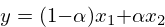
Where $x2$ are two values, and $\alpha$ is a fractional value between 0 and 1. The $\alpha$ values determines the distribution balance of the two values. When $\alpha = 0$, it is entirely $x_1$, and when $\alpha = 1$, the value is $x_2$.
The fractional (alpha) value is obtained by taking the lower bits portion of the current fixed-point phase position, and normalizing it to be a floating-point value between 0 and 1.
fract = (phs & osc->mask) * osc->inlb;There are now all the parts to do the interpolation. It turns out the equation above can be simplified further to shave off a multiply operation.
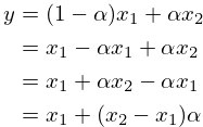
Which then gets translated to the following C code below.
In this step, the output is also being scaled by the
amplitude amp.
out = (x1 + (x2 - x1) * fract) * osc->amp;And now the sample has been computed! To wrap up, the
internal phase amount lphs is updated and masked to
prevent overflow.
phs += osc->inc;
phs &= SK_OSC_PHASEMASK;
osc->lphs = phs;