Contrenot Assembly
2016-11-30
As mentioned in my previous posts, I am in the middle of a quarter-long project to build an interface inspired by an upright bass. Here is an update. This really should have been two posts, but I've been working, so here's just one post.
As it currently stands, the Contrenot is basically assembled. It makes sound, and is in reasonably good shape. As a bass player, I find it to be a familiar interface. Bystanders (non-bass players) that tried to play the instrument had a harder time playing with the instrument. To me, this is a big success: I wanted my years of experience playing classical bass to translate to electronic sound.
The name "Contrenot" comes from the name "contrebass" and "martenot", the pull-string electronic instrument where I have drawn the most inspiration (the creation of which was inspired by the cello). Contrary to what the name suggests, the Contrenot does not (and will not) sound like a bass. Instead, I plan to produce a more soloistic sound in a higher register.
Many many hours were put in to get to this point. I will pick up where I left off.
Buying Supplies
After building a bow prototype the week before, it was time to buy lumber for the body. This meant a trip to the local home depot.
At the store, I spent a lot of time laying wood out on the floor and measuring it to get the right width. The picture above shows one of the layouts I did, which included the approximate placement of the bow and endpin. Unfortunately, I did not end up going with those oak sides... they were a bit too expensive for this prototype.
Initial body assembly
After purchasing the wood, I immediately went to work assembling body. The 2x4 planks were cut to size to build a neck and an endblock for the endpin. The hole I made for the endpin was not straight, which is why it is crooked in the picture (rough prototype yay).
The picture above show the instrument a little bit in the future, with the arduino, perfboard, and components mounted.
Electronics
With the body constructed, it was time to focus on the electronics. First, all the sensors were tested individually with the breadboard:
- The linear softpot was fairly easy to hook up to an analogue pin for reading.
- The linear FSR was a little bit more finnicky for me to get set up. The pins on these are not the greatest.
- The 16-bit adc from Adafruit was mostly easy set up thanks to the tutorials available. Getting the linear softpot hooked up took some experimentation with resistor size to get the maximum resolution. I ended up getting approximate 20,000 steps. Compare that to the wimpy 1024 steps you get with the 10-bit ADC on arduino.
- The rotary encoder was a later addition to testing. I purchased the 200 p/r encoder from sparkfun. Lots of ups and downs with this component. More on this later..
After all the components were tested, I began transfering the breadboarded circuits to a perfboard. Breadboard layouts can be kind of misleading, and dont transfer exactly to the perf board. It took me three tries to figure that out (as a side effect, I got a lot better at soldering!)

After multiple attempts, I was finally able to get a perfboard working. It is displayed above. In retrospect, I do regret using single wire instead of stranded wire. A learning experience indeed.
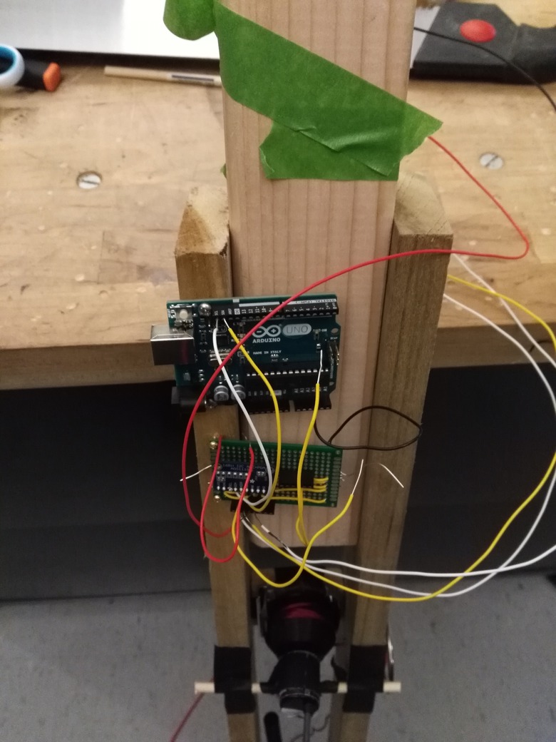
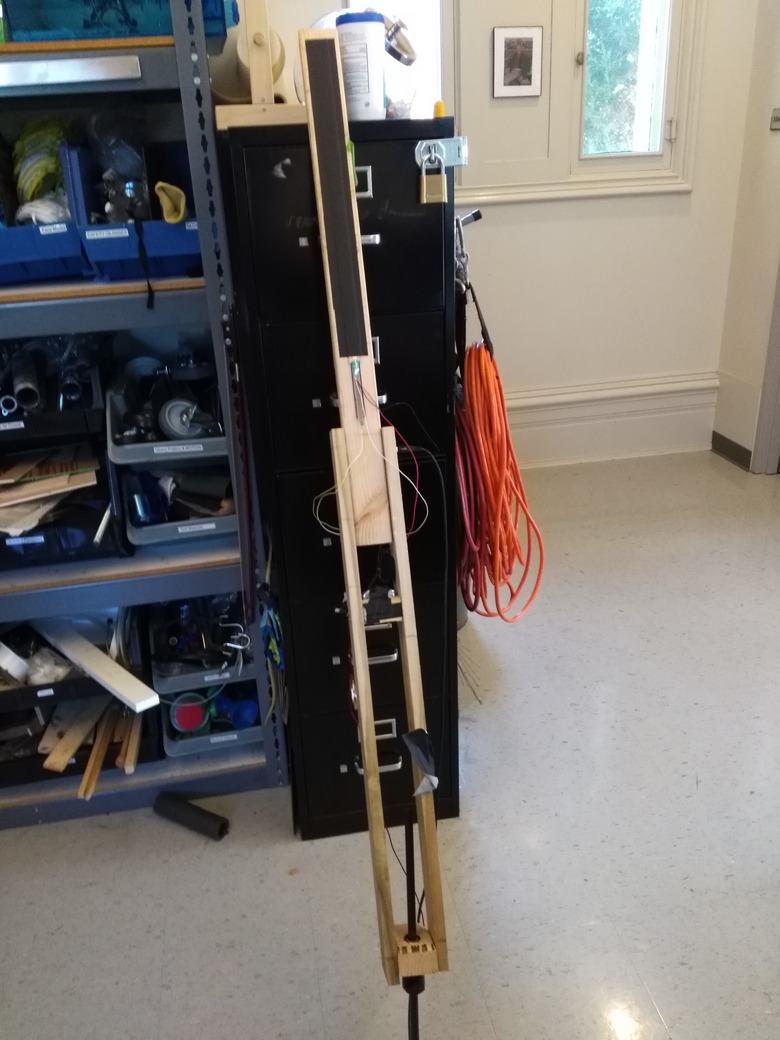
Speaking of wires, the picture above shows the perfboard and arduino wired and mounted on the body. A mess (did I mention this was my first real hardware project?), but it works!
Fitting the new encoder

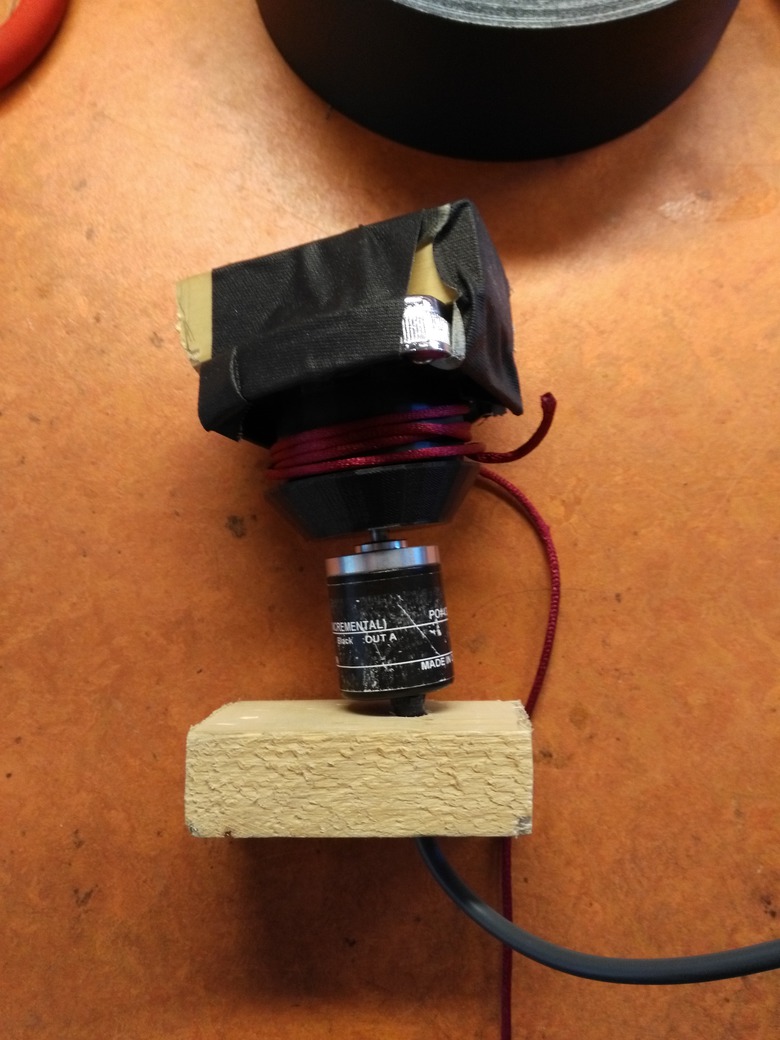
Since progress was faster than planned, I decided to try replacing my griffin knob with a rotary encoder for better resolution (and to have one USB cable). I ended up buying a 200 P/R rotary encoder off sparkfun, designed mainly for use in robotics. It is displayed above being fitted with a custom 3d printed knob I designed for it.
Man. This rotary encoder was almost more trouble than it was worth. For starters, I realized after purchasing it that it could not detect direction, only distance. This turned out to be more than fine for me: I did not need direction, and it ended up being much more simple component to work with.
There were also several points where I thought I had broken the encoder. I was so convinced of this that I went ahead and bought another encoder with rush delivery. It turns out that I did not break the encoder. It was just a really hard to find bug in my code that made it look broken. Oh well.
The encoder was a big improvement over the griffin knob, and had much more resolution. So much resolution, that the arduino was not fast enough to read it! I ended up having to hook the encoder up to a hardware interrupt. After I did that, I found that serial was also way too slow to do anything related to velocity. I went back and wrote more code that utilized the onboard timers to very precisely measure the distance between pulses in the encoder, and sent those measurements over serial. With lots of smoothing and math, I was able to implement some very satisfying smoothing.
After thinking I had broken the encoder, I went back and rethought how to fit the new encoder into the body. The old way above required sending the cord through a hole. I felt this design put too much strain on the cord, which caused it to "break". As a result, I ended up designing a much better system.
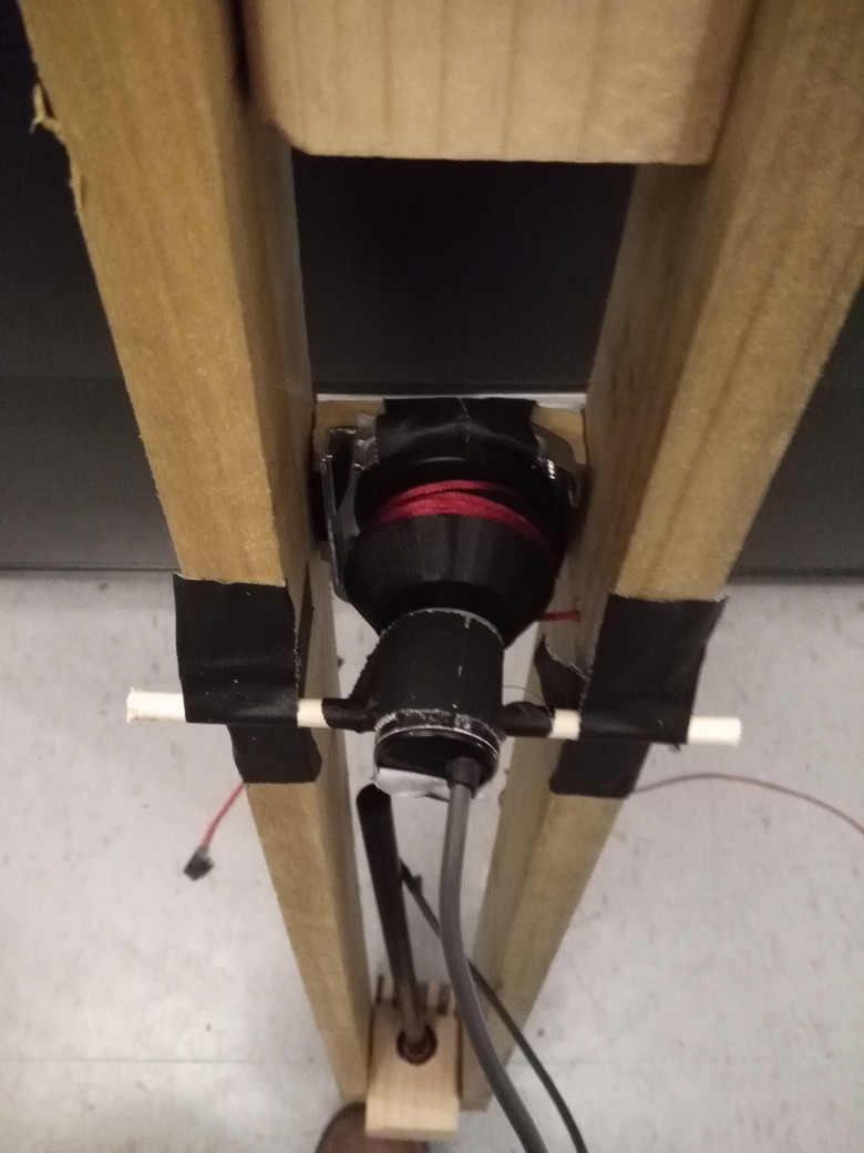
The picture above shows the new layout. The encoder and spool were flipped 90 degrees, and dowel rods were added to hold the encoder in place. Less stress was placed on the cord, and winding the spring ended up being much easier to do. Adjustments could be more nuanced, so the pull was a lot smoother as well.
Softpot callibration
With all the components working, it was time to get some test sounds created, starting with the softpot. To my disappointment, I found that while I had many bits of resoltion in the softpot, those bits were not evenly distributed. 90% of the bits were clumped in 25% of the space in the top. This lead to a few attempts to remap the signal to make it more linear.
My first thought was that the distribution logarhithmic, so I fit an exponential equation to some data points that I measured. The plots I made highly suggested a log curve, and the math I threw at it to make it linear seemed to help:
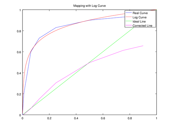
When I actually applied the math, the clumping I had witnessed before was gone, and I had achieved some really rough callibration: a value 0.5 was actually halfway on the board.
Still, there were issues. While the softpot was far more linear, it was not linear enough for musical purposes. I tried mapping a two octave scale onto it, and the steps between them varied greatly. Darn.
My next option was to use brute force and sample many steps of the softpot, and construct a linearly interpolated table. I created 50 ticks, 1cm appart, and measured their values at each point, and used this to build a weighting table that would warp the incoming values. This turned out to also be a bust. I was several hours into work that day and very frustrated, so I went to find dinner.
While walking towards dinner, I began to rethink about some of my thoughts regarding resolution and frequency, and came to some conclusions:
- This soft pot is going to be just used for pitch: 24 semitones to be exact.
- The most important thing is not high resolution, but being able to play with vibrato
- Perceptually speaking, how many subdivisions does one really need per semitone? 10-15 subdivisions is probably fine.
- In total, all I would really need is 384 steps, which is way less than 10 bits offered on the arduino ADCS (and here I am going out of my way buying a special 16-bit ADC for many bits!).
- I actually can afford to lose some bits
- Getting 24 steps mapped accurately takes priority over fine tuning
And with that, I rushed back to the lab to implement my new solution, which attacked the problem from a musical angle. This solution involved using the log function I tried initially, and then downsampling the high-res input signal to have a range of 0-1023, and feeding that into a lookup table. The look-up table would then be a map expressing which note should be playing. I marked out the and measured the positions I wanted for each note, making sure there was enough wiggle room for vibrato. With the map constructed, I was able to dynamically infer the size of each region. This was then used to subdivide the semitone into equally spaced positions.
And guess what? It worked like a charm.
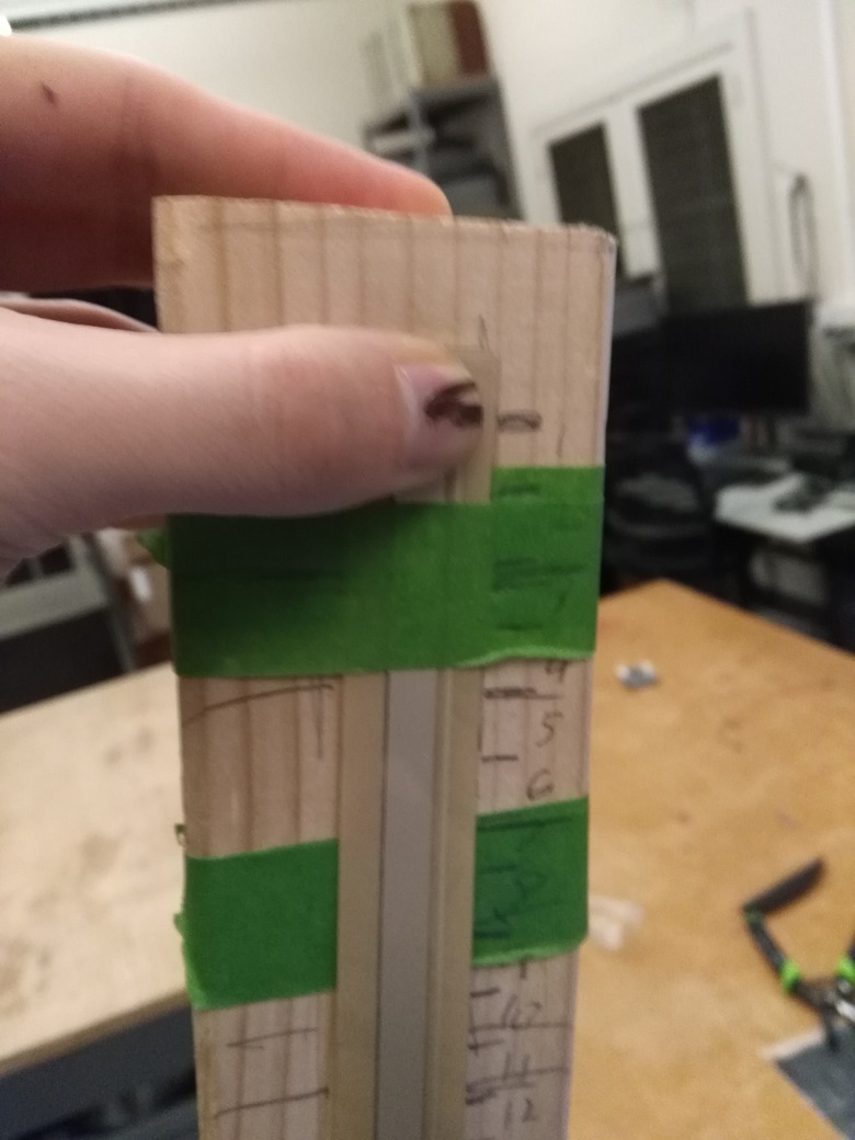
I placed some Gaffers tape over the softpot to improve the accuracy of it and to make it easier to play, as seen in the picture above.